OVERVIEW
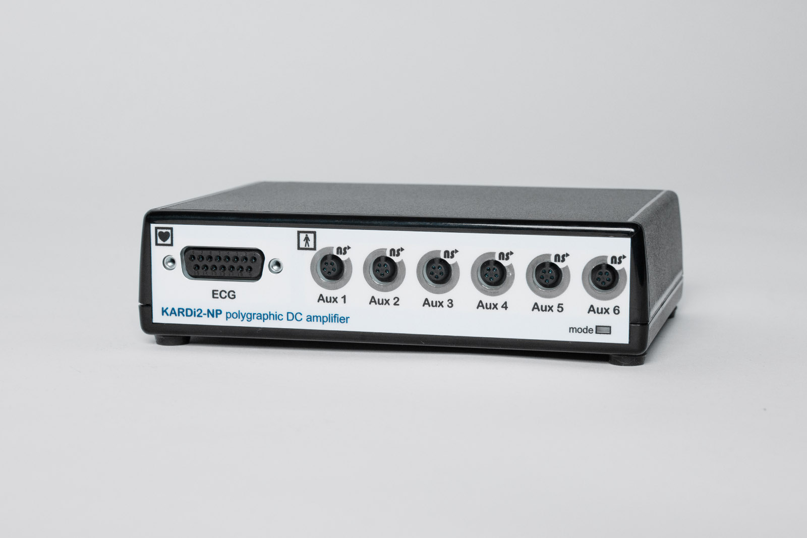
KARDi2-NP is a compact computer-based polygraphic amplifier designed for biomedical research and development. The device supports up to 6 ECG channels and up to 6 universal active sensors, enabling comprehensive recording of a wide range of physiological parameters.
The sensor channels are galvanically isolated from the ECG channels, ensuring compatibility with electrophysiological measurements and patient safety. In addition, the device provides two digital inputs and two outputs for synchronized registration and external event generation in biofeedback systems.
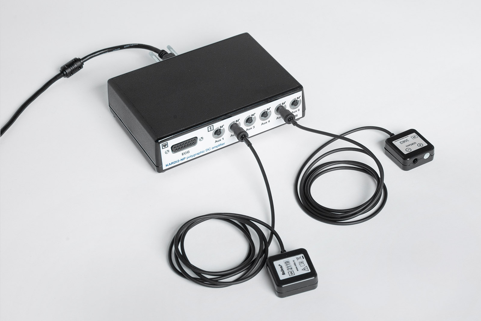
KARDi2-NP is compatible with the NeoSens series of biomedical sensors, including:
- respiratory sensors (RESPsens-MRI chest sensor, ABsens abdominal sensor, TRsens nasal/oral thermometric sensor);
- galvanic skin response sensor (GSRsens);
- accelerometers (AXsens, AXsens-3D);
- photoplethysmographic sensors (FPsens);
- EMG sensor (EMGsens);
- visual stimulus synchronization sensor (VGAsens);
- specialized sensors for impedance cardiography (IMPsens) and acoustic signal recording (SHOOTsens).


SOFTWARE
The KARDi2-NP system is supported by three software solutions: EScreen, NeoRec, and Cardiovisor.
- EScreen is designed for ECG recording and analysis. It supports standard lead configurations (12-lead, 6-lead, Frank orthogonal, Neb leads, differential), continuous recording up to 240 minutes, automatic and manual parameter measurement, rhythm analysis, and report generation. The software provides power line filters, event marking tools, R-R interval plotting, data export to text and open formats (MIT wfdb, EDF, BDF), as well as heart rate variability (HRV) analysis with an additional module.
- NeoRec is used for recording and analyzing biosignals. It supports saving in EDF+, BDF+, and GDF formats, as well as real-time data streaming via Lab Streaming Layer (LSL) for integration with MATLAB, EEGLAB, OpenViBE, and other solutions.
- Cardiovisor provides automated processing and visualization of ECG, generation of color maps of myocardial electrical activity, rhythm analysis, and rapid assessment of cardiovascular condition. Results are presented as reports and graphical maps suitable for clinical interpretation and documentation.
The combined use of these software solutions allows flexible organization of physiological signal recording and analysis, integrating ECG, EEG, and specialized methods of cardiovascular assessment.
SPECIFICATION
| Parameter | Value |
| General channel input characteristics | |
| Digitalization | Sigma-delta modulation with a frequency of 2048 kHz synchronously on all channels |
| Digital signal processing | Using application software. Filtering and decimation to output rates of 250, 500 (by default), 1000, 2000, 4000 or 8000 Hz (24-bit) |
| Passband | The lower band of the signal is ALWAYS 0 Hz (DC) - the required time constant is generated by software on the computer. The upper limit band of the signal at the level of -3 dB corresponds to 75, 150 (by default), 300, 600, 1200, 2400 Hz with a nonlinearity within 5% at the level of 50, 100 (by default), 200, 400, 800, 1600 Hz depending on frequency issuing readings. |
| ECG channels | |
| Number of ECG channels | 6 monopolar. |
| Input stages | DC amplifiers Input impedance greater than 70 MΩ. Constant quality control of electrode connections. Defibrillator impulse protection. |
| Input dinamic range | Switched by software independently for each channel. Can take values from the range ±820 mV (4 μV), ±410 mV (2 μV) (by default), ±205 mV (1 μV), ±100 mV (0.5 μV), ±40 mV (0.25 μV) , ±20 mV (0.15 µV) |
| Noise | Less than 15 µV p-p or 3 µV rms (0.5 to 75 Hz) |
| Checking the connection | Using application software. Continuous monitoring during recording via DC offset measurement |
| Galvanic isolation | Reinforced on the PC side and double reinforced with respect to additional sensor channels |
| Channels of sensors | |
| Channels | 6 differential |
| Input stages | DC amplifiers |
| Input dinamic range | Set by software from the range ±2.9; ±1.5 (by default); ±0.75; ±0.35; ±0.3; ±0.15; ±0.075 V. |
| Noise | Less than 80 µV p-p or 33 µV rms (0.5 to 75 Hz) |
| Powering of sensors | from amplifier, 3 VDC (±5%) max current up to 15 mA per probe with electronic protection |
| Galvanic isolation | Reinforced on the PC side and double reinforced with respect to additional sensor channels |
| Trigger channels | |
| Channels | 2 connectors for 2 TTL input and 2 TTL output |
| Input-output trigger connector | 3.5 stereo plug for connecting 1 input and 1 output triggers |
| Digital input | TTL levels: Low Uil <+0.8 V, Iil > -2.1 mA High Uih > +3.5 V, Iih > -0.1 mA |
| Digital output | TTL levels: Using application software. Low Uol < +0.4 V, Iol > -1.6 mA High Uoh > +2.8 V, Ioh > 0.5 mA By default, output trigger channels are High. |
| Trigger status | Synchronously with the issued channel readings. Accuracy ±0.5 reading Simultaneous latching |
| Galvanic isolation | Enhanced isolation from all channels. The triggers are located on the PC side. |
| General | |
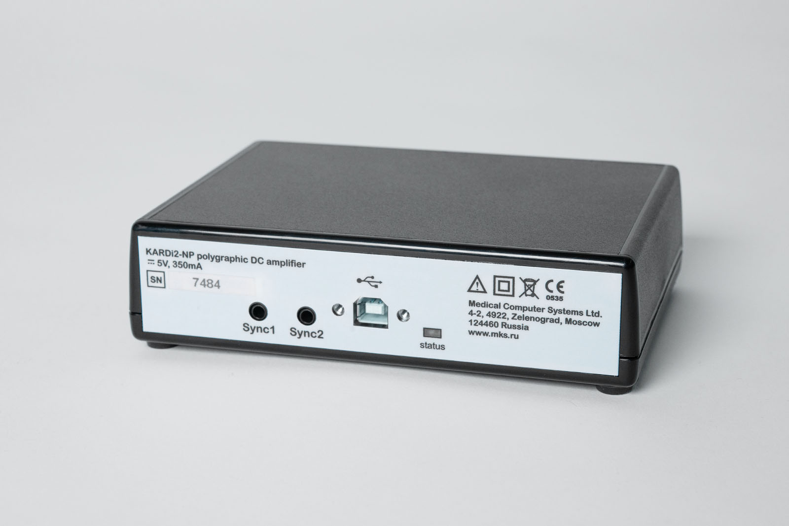
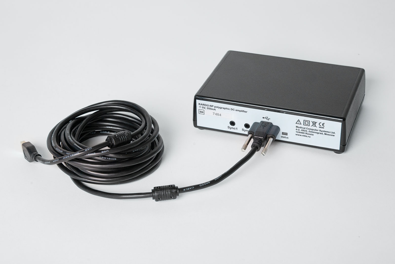
| PC interface | Via USB interface, V1.1, 2.0, 3.0 Full Speed Mode, B-type connector |
| OS | Windows XP and higher |
| Connection indicator (status) | Flashes 2 times when connected |
| Consumption current | < 350 µV |
| Supply voltage | ±5 V from USB |
| Mode indication | 2-color indicator light off – sleep mode green – no error, active mode red – internal error |
| Enclosure dimensions | 155 x 110 x 45 mm |
| Сable length | not less then 3 m |
| Weight of the amplifier | < 300 g |
| Time of continuous work | > 8 hours |
| Mean useful life | 5 years |
| (Undefined variable: texts/commonParamVariables.param_climateGroup) | - |
| Storage conditions | +5ºC...+40ºC |
| (Undefined variable: texts/commonParamVariables.param_TransportConditions) | -50ºC...+50ºC |
| (Undefined variable: texts/commonParamVariables.param_mechanicalResistance) | - |
| Safety | - |


PHOTO